HD3 is not an independent method of video compression! It is a set of algorithms that is implemented before the compression of a video file (pre-processing) and another set of algorithms that is implemented after the decompression (post-processing).
The idea of HD3 bases on an observation that a video image can be divided into a movable and immovable part. Due to the nature of the human sense of sight, man sees better images that do not move. On the other hand, we see moving objects less sharply and fast moving objects even worse (usually we can only roughly determine the shape and dominant colors). If so, then the objects still and moving can have different spatial resolutions and we would not be able to notice it.
The starting point for the development of HD3 technology was a patent application developed by one of us for the Advanced Digital Broadcast company in 2011 –EP2555521.
In this application is described the method of reducing the resolution of video frames, involving the sequential selection of pixels from the original frames into smaller “transporting” frames. The original frame is divided into blocks, for example of 3 pixels wide and 2 pixels high. Each block then, consists of 6 pixels. The transporting frame is constructed in such a way, that from the original frame, 1 pixel from each block is taken. For instance, from the first frame we take pixels with coordinates 1,1 (in the block), from the second frame pixels with coordinates 2,1, from the third 3,1, from the fourth 1,2, from the fifth 2,2 and from the sixth 3,2. From the seventh original frame we again take pixels with coordinates 1,1 and so on. In this case, a sequence consists of six transporting frames. If the original frame had “Full HD” resolution, which is 1920×1080, then after the reduction transporting frame has a 640×540 resolution. Therefore, new (transporting) video stream has 640×540 resolution which means that it has 6 times less pixels in every frame. If now, we compress it for example with h264 codec, we get a significantly smaller file than the original Full HD stream compressed with the same codec.
The reverse process involves the reconstruction of the output stream from the transporting stream in such a way that it has the same resolution as the original stream (in our case Full HD). The resulting frame is made of pixels from six consecutive transporting frames. The pixels from the first transporting frame are placed in a 1920×1080 frame, at the 1,1 coordinates in each 3×2 block. The pixels from the second transporting frame are placed at the 2,1 coordinates, from the third 3,1, fourth 1,2, fifth 2,2, sixth 3,2. After six transporting frames the video is fully reconstructed to the original resolution. If the image is static it is practically the same as the original one (differences are the result of the degradation caused by the h264 codec). However, if the image has a moving object in it, after such a simple reconstruction, we will see pixels of this object in six different places of the reconstructed frame (which is obvious because the frame had been reconstructed from 6 transporting frames created in 6 different moments of time). At this point, it is impossible to recognize a moving object. In order to properly reconstruct a moving object and place it in a proper place in a reconstructed frame, an information on which pixels show objects in move is required. To transporting frames should therefore be included information about movement in the form of a mask (binary bitmap) or a database containing a digital description allowing to reconstruct the mask.
At the top, on a dark car pixels of a moving object can be seen in 6 different places
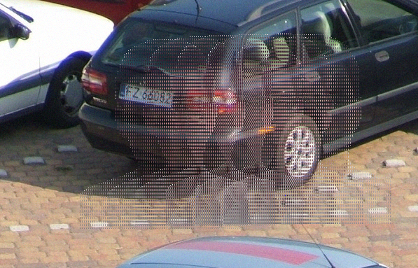
The enlarged detail showing that a moving object is present in six different places, thus individual pixels can be seen. The static part of the image is reconstructed properly.
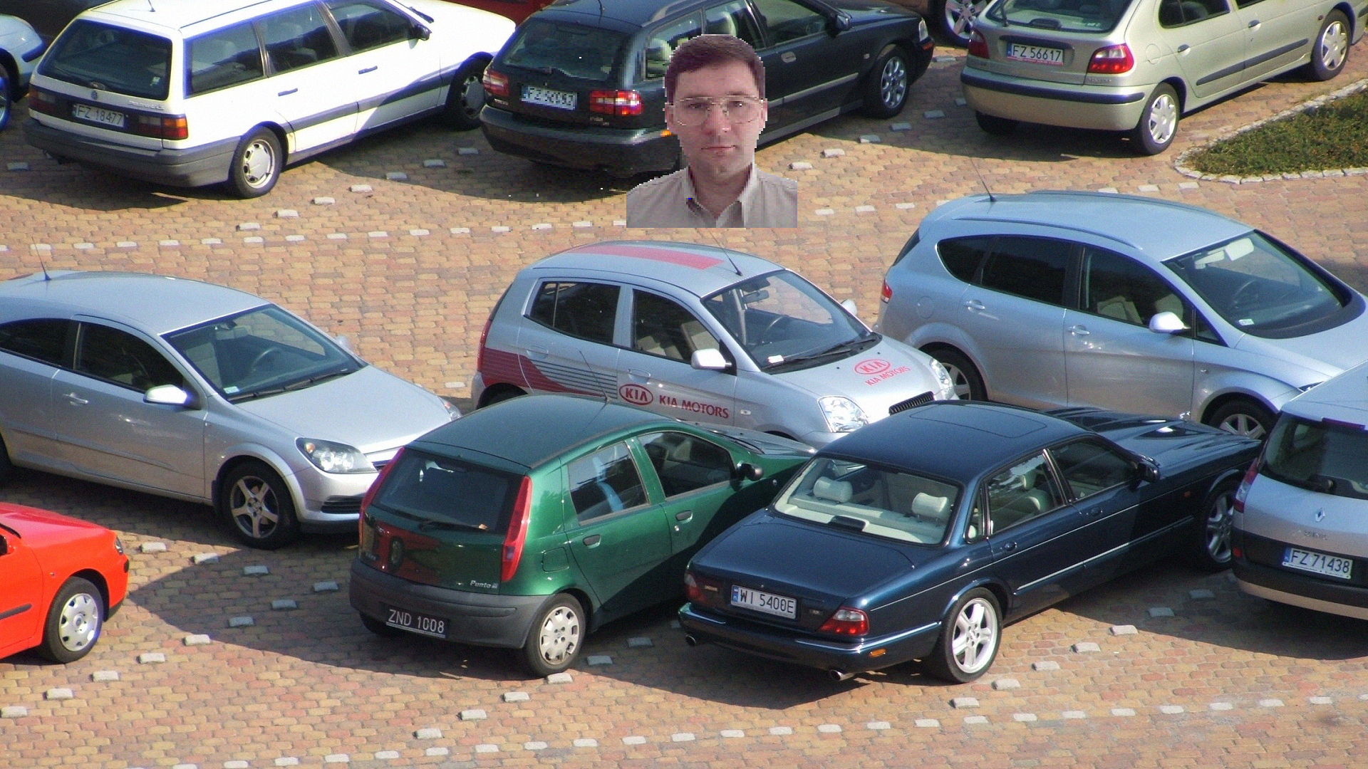
The same image after reconstruction of the moving object. The resolution of a moving object is clearly lower. This is immediately visible when you stop the film but not noticeable when the object is in motion.
Because our sample block is composed of 6 pixels, the mask must show the position of moving objects in 6 consecutive frames. This is necessary because the reconstructed frame contains the pixels of moving objects in their 6 consecutive positions. Reconstruction of the moving part of the frame consists of rescaling the transporting frame to the resolution of the resulting frame, same rescaling of the mask and copying to the resulting frame those pixels, from the rescaled transporting frame, that correspond to ones in the rescaled mask. As a result, in the places where a movement was detected (mask pixels have a value of 1 in those places) is placed an image, with a lower resolution (transporting resolution) rescaled to the original resolution. In the remaining places (where mask has a value of 0) is placed an image reconstructed from 6 consecutive transporting frames, so its resolution and amount of details is the same as in the original.
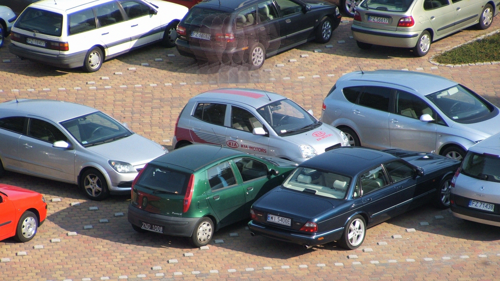
During my work at ADB I simulated a video image by moving a small bitmap (my picture) over a big bitmap (Full HD – parking lot picture), so I had complete control over the image and ease of analysis on how the HD3 method affects the image quality and whether it works at all. Simulation showed that it works.
After leaving the ADB and founding Patents Factory Ltd. we have taken this issue by developing a series of algorithms that make up the target HD3 technology.
1.EP13199638 – The method of motion detection in video images.
In order for HD3 to work properly an information on which part of the frame is moving and which is static, is necessary. We have tested various solutions and finally decided to patent the best one – MIN-MAX.
This method bases on memorizing the minimum and maximum values that each of the pixels in an image sequence, e.g. 16 consecutive video frames, adopt. If a pixel belongs to the static part of the image, then any changes in its color will only be a result of the noise in the image. If a pixel is in a place where there is motion, then its color is determined by the position of a moving object and the color change is much greater than caused by the noise. Therefore, we calculate the minimum and maximum color value for each pixel in the video image e.g. 16 frames back from the current one. Then we subtract the minimum values from the maximum values. The resulting difference shows how much the pixel colors have changed during the last 16 video frames. Those differences are calculated for individual color components (separately for red, green and blue). For the purposes of the algorithm, we assumed that the largest of the three differences (for R, G or B) will represent the pixel in further analysis. A better solution would be to calculate the RGB vector length, which is the square root of the sum of the squared differences, but the root requires many calculations which would result in a large computational complexity of the algorithm (for Full HD image it would be necessary to calculate 2M roots, 25 or more times a second, which equals 50M or more roots a second). For 4k image (3840×2160) it would be necessary to calculate at least 200M roots a second. Therefore, we decided to choose the maximum value method.
The next step is to compare our differences matrix to a certain threshold value Th. The threshold value should be calculated for video sequences, by calculating the parameters of the noise in the differences matrix (standard deviation, for those parts of the image where there is no movement, should be calculated), and then assumed that Th is slightly bigger than the standard deviation.
After comparing the differences matrix with the threshold value, we get a binary matrix, where in places with difference smaller than Th the value is 0, and in places with difference bigger than Th the value is 1.
The resulting binary matrix (logical) may contain a certain amount of pixels with a value of 1 resulting from the noise rather than movement, which is why it is necessary to filter it with e.g. salt and pepper type of filter, which eliminates single pixels with a value of 1 and fills holes (pixels with a value of 0) if they are surrounded by pixels with a value of 1.
Then, an analysis of the resulting binary matrix must be carried out and a database that identifies every object, made of pixels with a value of 1 must be created. This database, should include, for every object, structure defining: location of an object, its size and its shape (outline vector notation).
Database of detected objects in motion is included in the video transporting stream.
2.EP13199640 – Improving monitoring by simultaneously transmitting video and information about objects moving in the video.
This patent application is an expansion to the one described above. If we send data about objects in motion, we can supplement it with additional information allowing us to identify the cameras, their positions and orientation, and thus calculating position, velocity, acceleration and trajectory of moving objects. The assumption is that the cameras can operate either in simple systems, where the monitoring centers are equipped with monitors that just deliver the pictures from the cameras, or in complex systems, where the image from the cameras is further analyzed by computers. In both cases our camera can significantly improve the effectiveness and functionality of the system. In simple systems a camera can impose, on an image from the sensor, graphical symbols that indicate moving objects, and describe their parameters like velocity or acceleration. In this way, even if we have only a monitor we are able to observe significant, from the point of view of safety, parameters of the moving objects. On the other hand, in complex systems, we are able to reduce significantly the amount of computation and also increase the functionality of the systems, by combining data from multiple cameras. Next by triangulating we can determine position, velocity, acceleration and trajectory of objects in three-dimensional space.
The result is an optical moving objects detection system with a possibility of weapons or zoom cameras guidance on those objects.
In combination with 3D glasses, complex system will allow to create a three-dimensional presentation of the observed area.
3.EP13461571 – The method of visualizing the dynamics of movement in the video image.
It is an algorithm that shows, with the help of colorful masks imposed on the video image, velocity and acceleration of objects.
In the monitoring systems and particularly in places where there are moving vehicles and people, there may be a need for instant and intuitive assessment of the situation. Seeking a vehicle or man which is different than others (by a way of movement) in an ordinary video image is not easy. After applying colorful masks on the objects, symbolizing its past and future route (future relative to the reference frame that is in the past relative to the current frame) object that has different velocity or acceleration can be seen immediately. Similarly, you can see immediately which objects behave uncertain, changing velocity or acceleration every moment. The use of colorful masks has proven to be very effective. They allow to instantly read the dynamic characteristic of objects.
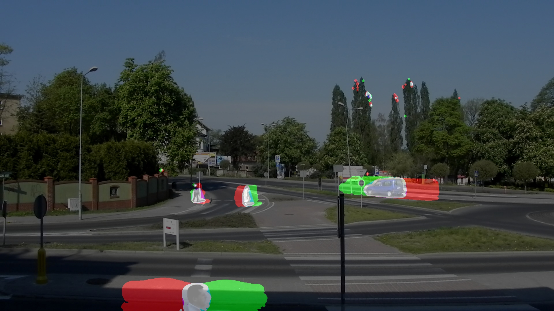
Video frame with masks imposed on objects, showing their past location (color red) and future location (color green). Clicking on this image will open the movie on YouTube.
Objects are highlighted in white. Color green shows where the object will move in the near future and color red shows which way the object moved in the near past. If the surface of the green mask is approximately equal to the surface of the red mask it means that the objects moves more or less with constant speed. If the green mask is bigger than the red mask, the object is accelerating and vice versa if it is slowing down.
The algorithm is simple. First, the brightness of the video is reduced by e.g. 50% by multiplying the color components of pixel by 0.5. Then, using the above described algorithm of motion detection, two masks showing the movement of objects are created: the first from the reference frame to minus 8 frames, and the second from the reference frame plus 8 frames. The first mask is the mask of past, and the second is the mask of future. For those pixels, that the past mask has a value of 1 to a frame retracted by 8 frames relative to the reference frame, we add 128 to the red component. For those pixels for which the future mask has a value of 1, we add 128 to the green component. For those pixels for which both masks have a value of 1, we further add 128 to the blue component to give a white backlight to a moving object.
This algorithm was not created in order to show the dynamics of movement. We developed it to calculate the velocity and acceleration of moving objects in the camera field of view. We need those parameters in order to pick optimal parameters for HD3 pre-processing. Showing the dynamics came to us by accident.
4.EP13461572 – The method of hiding irrelevant information in the video image
The ability of the human brain to analyze visual information is limited. According to our experiments, if the amount of detail in the image is substantial the brain eliminates a significant portion of the information and the person cannot see certain objects even though they have them before their eyes. Hence the idea to eliminate irrelevant data from the image shown to the operator of the monitoring system.
This algorithm hides (by making grey) those parts of the video frames that contain static information. In other words, after applying the algorithm the operator sees only moving objects. As a result the operator is able to see even small and very distant moving objects, which he was not able to see before.
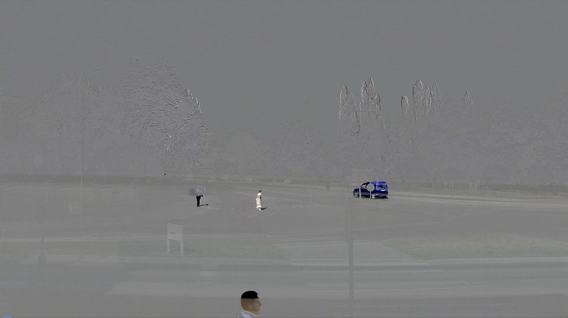
Video frame with a grayed static part. Clicking on the image will open the film on YouTube.
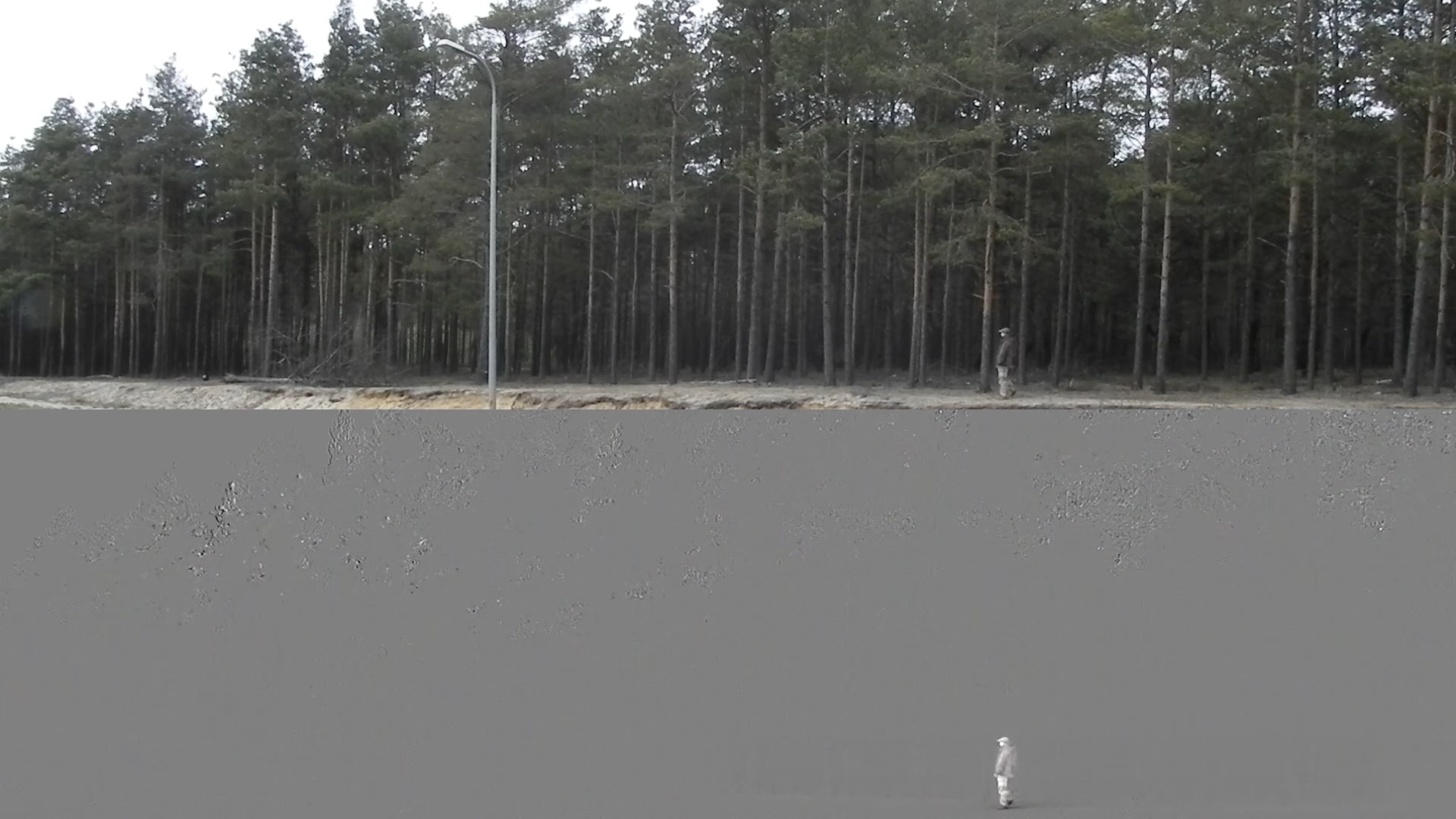
Video frame where the upper half shows the original image and the lower half grayed out. Clicking will open the movie on YouTube.
The algorithm is very simple. First we select a reference frame shifted e.g. 256 frames back from the current frame. Next, we calculate an average from e.g. 513 frames where the reference frame is the middle one. Next, we subtract a calculated average from the reference frame, divide the result by 2 and add 128. Wherever the reference frame is close to the average value, the result of subtraction will be close to 0, which is way after the addition we can observe grey color in those locations. Where the reference frame varies from the average value a difference can be observed, so moving objects can be seen clearly.
This algorithm was not made to hide the static part of the image. We wanted the algorithm to detect static objects (such as road signs and information boards) located between the camera and the moving objects (in the photo above you can see a gray mark on a blue car, which means that the mark is between the camera and the car). We discovered the visual effect while we were trying to determine whether the algorithm works properly. It proved to be so interesting, that in itself is an interesting solution for monitoring systems. Nevertheless, for the HD3 it is primarily a method of detection of static objects placed between the moving object and the camera. Narrow static objects (such as pipe on which a road sign is placed) located in front of the moving objects, thanks to the mask filtration can be completely eliminated. This causes visible distortion after post-processing (after the frame reconstruction).
The detection of static objects located directly in front of the moving objects helps to adjust the mask and prevent artifacts.
5.EP13461573 – Method of estimating dynamics of moving objects in the video image.
This solution is a derivative from work on the movement dynamics visualization. Algorithm allows to calculate velocity, acceleration and trajectory of objects. In case of a single camera parameters can be calculated only on a plane. In the case of two cameras at a known position and orientation in space, velocity, acceleration and trajectory can be calculated in 3D space. The calculations are carried out basing on an information about moving objects, made for each of the subsequent video stream frames. After detecting moving objects in the video frame and preparing a motion mask, that has pixels with a value of 1 only at a location where there is movement it became possible to draw masks showing the future and the past of objects in motion. Future mask is obtained by summing the N consecutive motion masks occurring after the middle frame (shifted backward N frames relative to the current frame). Past mask is formed by summing the N consecutive traffic masks that appear before the middle frame.
The result is two masks, where the objects have a larger surface area than on the motion mask. Each object from the motion mask correspond to analogical object on the Future and Past masks. We can calculate their surface expressed in pixels. By dividing the surface of an object on the Future or Past mask, minus surface of an object on the motion mask, by the surface of an object on the motion mask (for the middle frame), we obtain a number proportional to the velocity of an object. By dividing the surface of the object on the Future mask by the surface of the same object on the Past mask, we obtain a number proportional to the acceleration of an object.
Those calculations are only accurate if an object is moving transversely to the axis of the camera. If an object is moving at an angle to the camera it is either moving closer or away. You must enter a correction proportional to the angle at which the object is moving relative to the camera. The data after correction can be used to estimate the velocity and acceleration of the object. The acceleration can be calculated conventionally, by dividing the speed increase by a time interval in which the speed increased (or decreased).
The calculated speed and acceleration are proportional to the actual value of speed and acceleration and are not the actual values. It is necessary to calibrate the system to obtain information on how to convert received numbers to actual values. Conversion factors will be different in different parts of the image since they depend on the distance of objects from the camera. The most reliable results can be obtained by using two or more cameras and determining distances to moving objects.
In the case of a camera measuring the speed of vehicles that is placed over the road, perpendicular to it, the distance to the road is known and calibration of the system is very simple. It is enough to film a vehicle with a known velocity to determine the coefficient of proportionality.
6.EP14461519 – The method of sharpening and blurring images, with low computational complexity.
Our algorithm is characterized by unique simplicity which directly translates into low computational complexity. It comes down to few steps: first we calculate the derivative of the value of each pixel in the X-axis, creating a matrix of the same size as the frame designed to modify, then we calculate the derivative of the value of each pixel in the Y axis. Further we summarize the matrices of derivatives at X and Y. The resulting matrix is multiplied by a factor of proportionality K determining the strength of the effect, and subtracted from the original frame. As a result, we obtain sharpened or blurred frame.
7.EP14461520 – The method of reduction the video stream resolution and reconstruction of the original resolution.
Method is based on assumption that resolution of video frame can be reduced before compression if most of its surface have small number of details (high frequencies are absent after DCT transform). To make the process easier, before analysis of details density in the frame, the frame is modified by reduction of details density in places, where are moving objects. The faster is object’s movement the stronger should be blur effect in the place where that object is. Blur reduces density of details (high frequencies).
Because density of details can be different in different parts of the frame, the frame should not be scaled but transformed with morphing. Thanks that is possible to stretch frame in places where is more details and squeeze in places where is less details. The network of transformation is build base on the map of details density in the frame.
The network of transformation have to be attached to reduced video frame, for example in form of a table of coordinates of nodes. If identical network of transformation is used for multiple frames then it is attached only once.
Once the resolution of the frame is reduced, it can be compressed with video codec.
The reverse operation is made by decoding the frame with video codec, then rebuild network of transformation from the table of nodes and do reverse morphing transformation. As a result we will obtain reconstructed frame with the same resolution like original frame.
It is necessary to keep the same spatial resolution for all reduced frames of the GOP (Group of Pictures) from the I frame to the last frame before next I frame. Each GOP can have different spatial resolution. Also aspect ratio can be different. Because resolution and aspect ratio are variable in that concept it is not possible to watch such prepared movie with standard codec or player.
We created that method as an alternative to solution prepared for ADB company, to avoid patent violations.
8.EP14461539 – Method and system for sharpening or blurring an image.
This is an improved algorithm of a patent application EP14461519. The change is based on another method of calculating the derivative. Previously derivative was calculated by subtracting from the value of the pixel, value of a pixel which precedes it. As a result, the derivative is not calculated for that pixel but for the point that is located between the pixels used to calculate the derivative. After subtracting matrix of derivatives at X and Y appears a displacement of objects’ edges. It does not matter when the algorithm is used for regular use (e.g. to sharpen images before displaying on the screen). It may be of importance when sharpening is a fragment of image analysis algorithm.
Therefore, we used a different method of calculating the derivative. For a given pixel the X derivative is calculated by subtracting the pixel to the left of the pixel values on the right and dividing the result by two. Derivative of the Y is calculated in the same way. The rest of the algorithm remains unchanged. As a result, the edge shift effect disappears and the algorithm can be used in image analysis. In addition to noisy images we have proposed the use of a four-point finite difference instead of the usual. It decreases the impact of noise but unfortunately increases the amount of calculation. The user must decide when to use this variant.
V2.5
The above-described algorithms comprise the version 1.0 of the technology HD3. We tested it with the mathematical modeling method on a few selected test stream and came to the conclusion that it is necessary to improve the technology.
As a result, we developed more algorithms leading to the current version, which, for internal use, we describe 2.5.
We improved motion detection algorithm. The current version is more resistant to noise. Moreover we moved movement analysis to the side of the HD3 decoder. This means that it is not necessary to send the motion mask to the decoder. This improves the compression ratio.
We have developed an efficient algorithm that calculates the density of details in the image. On the basis of the results of its operations we have developed a measure defining the level of details in the video frame. This measure is then used for automatic selection of parameters and transformation of a video frame.
We have also developed another measure for evaluating the amount of movement in the image (number of objects, their size and speed), which also affects automatic selection of parameters and transformation of a video frame.
We have developed a filtration method that do not reduce the sharpness in areas where there is a lot of details while reducing distortions in areas where there are moving objects. Artifacts generated by encoding and decoding with HD3 become almost invisible.
We have developed three methods of encoding the transport video frames which are alternatively selected, depending on the value of the aforementioned measures. One method is chosen for encoding frames with lots of details and a small amount of movement and another for frames in which there is a lot of movement.
Finally, we developed a method for automatic selection of the degree of reduction of video frame. The degree of reduction is selected on the basis of the aforementioned measures.
As a result, we obtained the HD3 version, which dynamically adjusts to the content of the video image in order to maximize image quality.
We are testing this version on the video material with a resolution of 4K aka UltraHD aka UHD (3840×2160). H264 codec working together with HD3 allowed on average reduction factor of about 6 times (or about 83%) relative to H264 codec running without HD3.
We expect that for the video with a resolution of 8K aka Super Hi Vision (7680×4320) we will obtain a reduction factor at least 10 times (minimum 90%). Unfortunately we have not access to video content 8K of good quality (from the fixed camera) to check it.
We continue improving HD3.
Recently we invented new version, which do not reduce resolution in places where is the movement. It is too early to estimate reduction factor. We have to build mathematical model and use it to test algorithms.
The newly developed algorithms will be registered with the European Patent Office in year 2016.