
Common Observations
- Moving objects are seen less precisely than static objects
- An objects with higher speed of movement perpendicular to camera axis are less distinct.
- If in the field of view (FOV) we have large static areas with a lot of details and large and small moving objects, we “cannot see” (we are not aware of the existence) of the smallest moving objects “in the background” even though they are in the field of view
- If mentioned above static part of the video frame will be replaced with homogeneous background (e.g. gray) then we see (we are conscious of) ALL moving objects independent of their size and position on the frame (look here: https://youtu.be/5daJC3rcgoo and here:
https://youtu.be/O1dMJlpXr0Y ,original is here: https://youtu.be/2EbGQlcGM94). - If we remove the noise from the static part of the image and leave noise on the moving objects, the viewer will have the impression that the ALL PICTURE is devoid of noise
Thesis
Human’s brain needs some time to analyze all information from picture covered by FOV. Higher number of details in FOV causes that the more time is needed to analyze it. Moving objects quickly change their positions so the time to analyze their details is too short. It is why we (our brains) do not
see them precisely. It is a brain’s feature , not the eye. Probably because of limited image processing power, the brain accepts information about moving object, without information about its details. When predator starts moving to us, it is not important how many stripes or speckled spots there are, only what trajectory is and how far away it is from us. When our eyes follow moving object then we see it more precisely however we lose precision of remaining part of picture because for eye focused on moving object the background is moving (relative to that object).
If we will observe moving train from small distance (e.g. 2m) then we see blurred train watching in one point of field of view or we will see (not precisely) a piece of train on which we focus our eye (following that point on the train). The bigger is train speed the less precisely we see it.
HD3
We can reduce quality of moving objects in video , because we do not see it precisely anyway and viewer is not conscious of that. Frozen frame is an exception. On frozen frame areas with reduces details quality are visible.
Assuming that we can reduce details quality in selected areas of the frame we decided to reduce spatial resolution of the frame in those areas. In the rest of the frame we left unchanged resolution.
We consider that area is static if we are unable to detect movement in that area. It not means however that that there is no movement at all. It is possible that movement is present but is very slow. If slow movement is possible in “static” areas then such areas cannot be replaced by static background picture. Examples of slow movement in “static” areas are changes of the illumination, clouds movement, slow movement of the plants in the wind, etc. So, static part of the frame have to be coded in the way allowing on propagation of slow movement.
We considered that is possible significant reduction of data in video stream based on above assumptions. We named that method HD3, referring to MP3 where also are removed significant parts of data with acceptable quality of sound.
We considered that is possible significant reduction of data in video stream based on above assumptions. We named that method HD3, referring to MP3 where also are removed significant parts of data with acceptable quality of sound.
HD3 coding
The first step we need to make is detection of all movements based on group of frames . As the results we have an information about areas of frame with and without any movement.
Let’s assume that we have to reduce 16 times an amount of data from an input stream.
In HD3 it means that 16 consecutive frames from the input stream will be replaced by one HD3 frame with the same resolution. It means that output stream has the same resolution however the framerate is 16 times lower.
The frame is divided into 4×4 blocks for example. The number of pixels in the block must be equal to the reduction rate. For the reduction rate equal 16, the blocks could be 8×2,4×4,2×8,16×1,1×16.
For example let assume following block of pixels
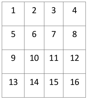
Next we copy pixels from 16 consecutive input frames to one output HD3 frame in following way:
pixel (1) from 1 st frame to pixel (1) in output HD3 frame ,
pixel (2) from 2 nd frame to pixel (2) in output HD3 frame,
pixel (3) from 3 rd frame to pixel (3) in output HD3 frame,
….
pixel (13) from 13 th frame to pixel (13) in output HD3 frame,
pixel (14) from 14 th frame to pixel (14) in output HD3 frame,
pixel (15) from 15 th frame to pixel (15) in output HD3 frame,
pixel (16) from 16 th frame to pixel (16) in output HD3 frame,
Of course could be used other pattern of copying as shown below
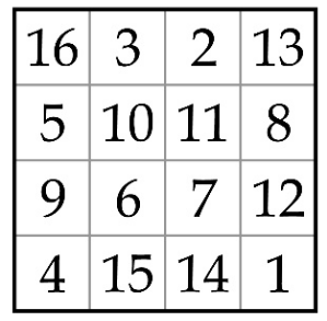
the number shows from which input frame comes copied pixel to the output HD3 frame at the same position. Our experiments show that a random pattern or a magical square pattern gives a better (more naturally) looking propagation of slow motion in case of leaves or branches of trees.
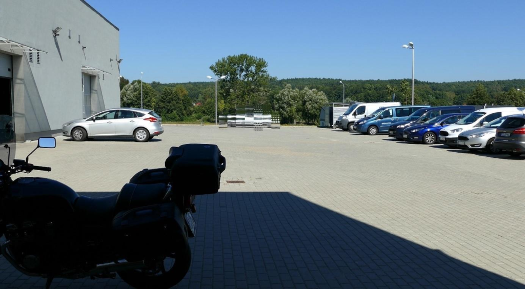
So, now we build the HD3 frame based on 16 input frames. The static areas looks good, however objects in motion have disappeared. Instead You can see strange “spots” in places where objects are in motion on original frames. Pixels of objects in motion have been dispersed in the area in which objects move. The faster the movement, the larger the dispersion of the object.
The output HD3 frames are then coded with one of the commonly used codecs (e.g. h264 or h.265). If the pixels of the object in motion are dispersed then the object will be so degraded during compression that it is unlikely to be recognized after the reverse operation (i.e. decoding the codec and then the HD3 postprocessing).
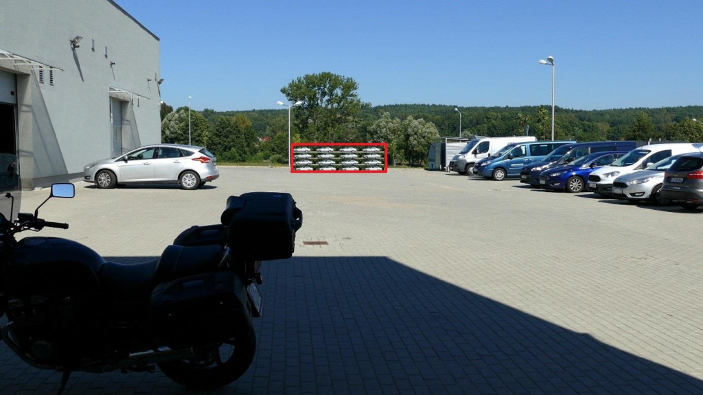
So, we have coded the areas with any movement inside based on 16 consecutive frames (Region of movement ROM) in different way. We did it that each ROM we enlarge it to the rectangle described on it. Next, we cut this area from the original frame No. 1, we scale down 4x on the X axis and 4x on the Y axis and then place it in the upper left of the same area in the HD3 frame.
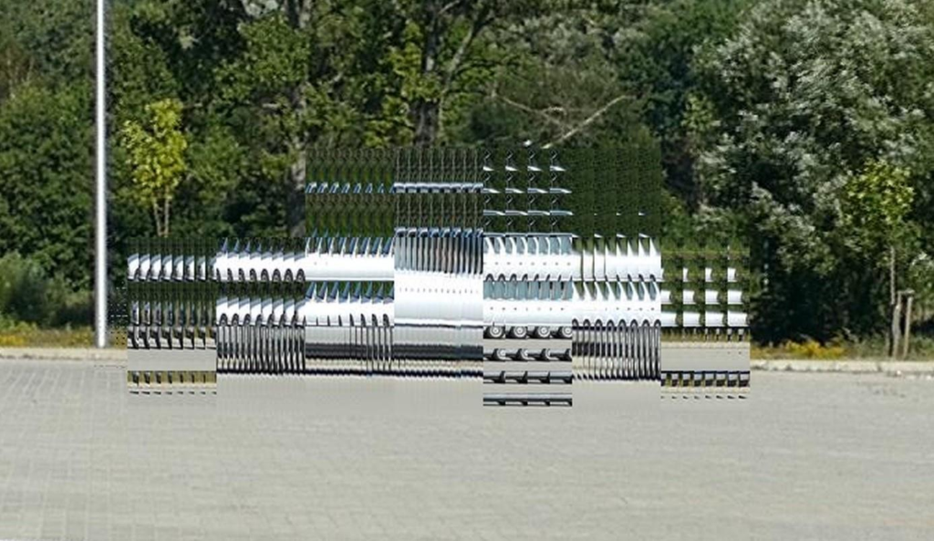
Next, we cut this area out of the original frame No. 2, scale down 4x in the X axis and 4x in the Y axis and then place it to the right from the moment before pasted fragment from the frame No. 1. The scaled piece from frame 3 is placed to the right of the frame cutout 2 and so on. The result is shown in Figure 1.
Of course, scaling down fragments degraded their quality. However, with a correctly selected reduction coefficient, this is acceptable to the viewer. The size of the reduction factor strongly depends on the resolution of the original video frames. Our experiments show that for a 4K resolution the maximum (acceptable) reduction factor is 6. For a resolution of 60 million pixels (12.000×5.000) as in our experimental HD3 camera, the reduction factor is 16.
The 4×4 reduction is not always optimal. If the object has many vertical lines, a 16×1 reduction (16 times vertical and without horizontal reduction) or 8×2 can be more beneficial. For an object with a large number of horizontal lines, a 1×16 or 2×8 reduction will be more beneficial. For the reduction rate of 16, we have 5 options for scaling objects (1×16, 2×8, 4×4, 8×2 and 16×1). In our experimental HD3 camera, we choose scaling by scaling a given image fragment down with all 5 variants and then back up. Then we subtract the reconstructed fragments from the original one and add the squares of errors. We choose the variant that generates the smallest sum of errors.
It may happen that the scaled fragment contains a lot of details (high frequencies) that will degrade. Then, the deteriorated quality of the scaled fragment will become visible.
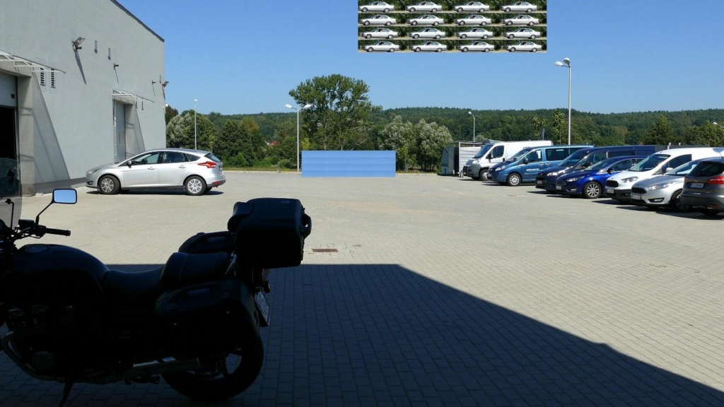
To prevent this, we use a trick based on replacing a fragment of an image with a very small amount of details (eg a fragment of the sky) with a fragment containing motion and vice versa.
In Figure 2, you can see that the sky contains a fragment containing a moving object built of 16 fragments cut out of the original frames. If the area with a small amount of details is large, fragments cut from the original frames do not have to be scaled at all. A veiled portion of the sky is treated like an area with detected motion and contains scaled sky fragments from the original frames. It is placed in the place where the fragments with the object in motion were copied.
The HD3 postprocessor behind the video decoder must recreate both fragments instead of one, but in the sky degradation is invisible because this area did not contain details and the reconstructed object in motion looks much better because it was only slightly or not scaled up at all.
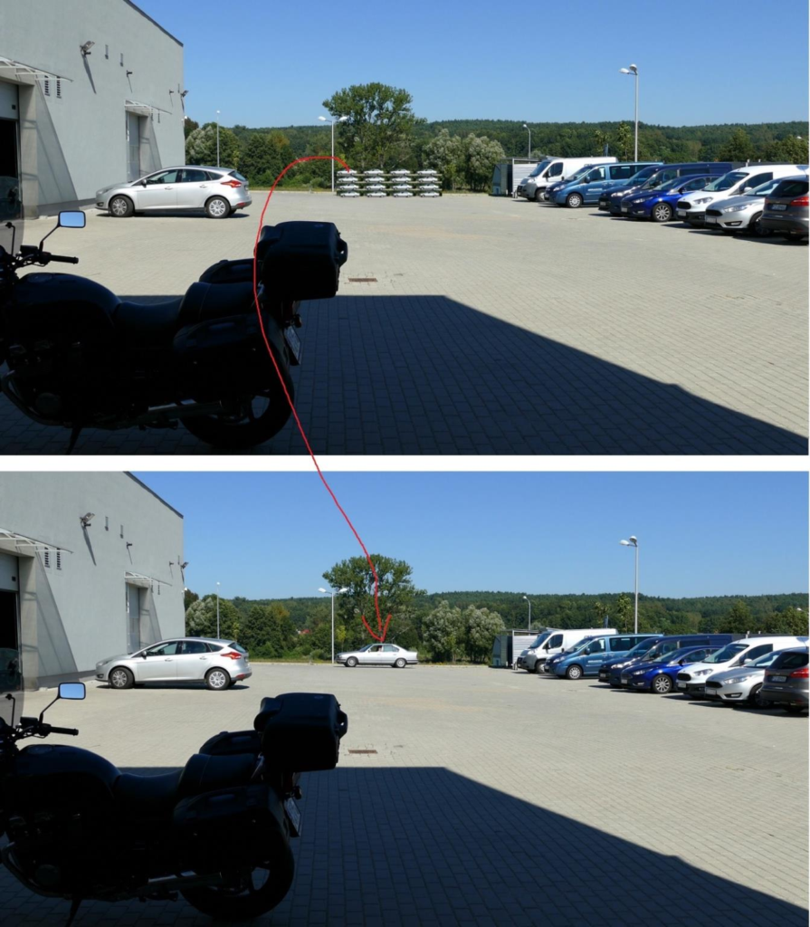
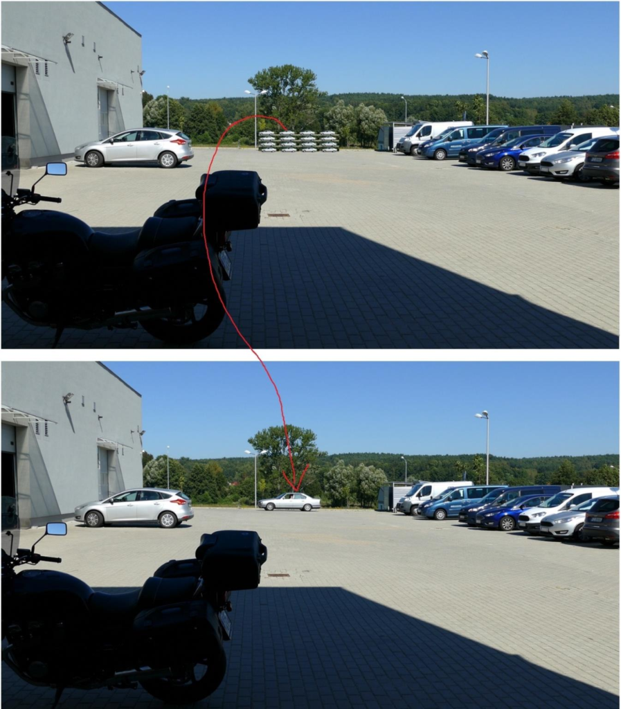
The HD3 coding described above works however sometimes degradation of the background behind the object in motion is visible. For example, in the above image, these may be trees or shrubs behind a silver car. Since the entire rectangular area in which the object is entered is scaled, the background fragments behind the object are also scaled.
To minimize this phenomenon, we have divided the area scaled into blocks (eg 64×64 pixels) and each block is scaled separately with the selection of optimal scale factors for the X and Y axes.
As a result, we obtained less distortion brought by the scaling process. Of course, block scaling and transposition of scaled areas into a static part with a small amount of detail can be used together.
If the movement of the object is relatively slow (measured in pixels per frame), a smaller number of areas taken from the original frames can be encoded in the area of motion. For example, in the frame composed of Fig. 1, 16 scaled down areas from the original frames were coded in the motion region. However, if the vehicle’s movement was slow (eg 2 pixels per frame), then it would be possible toencode in the HD3 frame not 16 original motion areas but smaller number, e.g. 8 of them, at the same time reducing their reduction. As a result, the image quality in the area where the vehicle is moving will be higher at the expense of movement mapping. At very low speeds, multiple displaying of a given fragment will be invisible to the viewer. Of course, this area of movement must be accompanied by information that it is composed of N2 original areas where N2 <16. Information on how to decode this area must also be included (eg display each enlarged component area 2 times instead of 1 time).
A similar situation occurs if the motion appears only on a part of the original frames that make up the HD3 frame (e.g. on 3 out of 16). Then the motion area with detected motion should contain, for example, 4 original areas (1 without movement and 3 with movement). The degree of reduction is smaller and the quality of the reconstructed area is higher.
After encoding HD3 frames according to the above method, they should be compressed, e.g. with the H264 codec, and recorded or sent.
On the decoder side, they should be decoded with the same codec and then reconstructed.
Reconstruction
The working frame should be created by copying the first HD3 frame to it. Then, one by one, enlarge the fragments of the motion areas of the first HD3 frame taken from the first original frame and place them in the working frame in the place where they were placed in the first original frame. After this operation, copy the working frame to the reconstructed frame Nr1. It can be displayed now.
Now, one should enlarge the parts of the first HD3 frame’s motion taken from the second original frame one by one and place them in the working frame in the place in which they were placed in the second original frame. After this operation, copy the working frame to the reconstructed Nr2 frame. It can be displayed.
These steps should be repeated N times where N is the number of original frames encoded in the single HD3 frame. As a result, we will get N frames with a resolution identical to the original one. Because the framerate of the HD3 frame stream was N times smaller than the original one, after reconstructing the N frames from one HD3 frame, we get the original framerate back.
Next, download the second HD3 frame. This time, we copy only those pixels of the static part that come from N + 1 of the original frame to the working frame (for example, pixels (1,1) from each 4×4 block). We reconstruct motion areas identically to the first combined frame. After this operation, copy the working frame to the reconstructed N + 1 frame. It can be displayed.
These steps should be repeated N times. As a result, we will get another N frames with a resolution identical to the original one.
With the third and subsequent HD3 frames, we proceed in the same way as with the second HD3 frame. We get a reconstructed video stream with a resolution identical to the original and framerate identical to the original one. Static regions have their original resolution preserved, not degraded by HD3 coding, and motion areas have a reduced amount of detail, but this is not very visible.
HD3 is lossy compression. However, the high quality of the reconstructed static areas makes the viewer feel that the whole picture has such a resolution. The inability of a human to view moving objects in detail makes the viewer unaware of the deterioration of the moving objects.
HD3 is predisposed for use with very large video resolutions like 8K and more. In contrast to existing video codecs, it allows significantly reduce the amount of data in the video stream that it is feasible to transfer images from cameras with a resolution of several dozen, several hundred and even several thousand Megapixels over the existing telecommunications infrastructure.
The HD3 restriction is that the camera should not move. That is why we believe that these cameras are predisposed to monitoring systems and not to the transmission of movies. The exception is sports events or concerts, where you can use several immovable HD3 cameras to show the ENTIRE stadium, or the WHOLE stage. Camera movement is not necessary because very high resolution allows you to perform digital zoom to show the viewers interesting details. And because the whole frame is sent to the viewer, the viewer can be the deciding person where and how to zoom.
All codes are open now. Link to GIT repository is here: source code
Files to download:
- Description [PL]: description.pdf
- Code documentation [PL]: implementation.pdf
- Prototype of camera [PL]: camera.pdf